Good price  online

products details

Home > Products >
Hybrid Stepper Motor
>
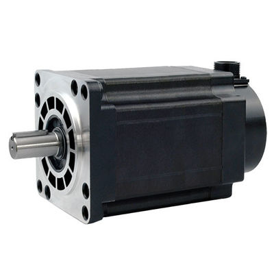
3110HS1600 3 Phase Hybrid Stepper Motor

3110HS1600 3 Phase Hybrid Stepper Motor

Brand Name: PRMCAS
Model Number: 3110HS1600
MOQ: ≥50pcs
Packaging Details: 1pcs for each carton
Payment Terms: Company account based T/T
Detail Information
Place of Origin:
CHINA
Certification:
CE, ROHS, CCC
Frame Size:
Nema 42, 110mm
Phase:
3 Phase
Step Angle:
1.2°
Angle Accuracy:
0.06°
Rated Current:
6.5A
Holding Torque:
16.0N.m
Wires:
6
Highlights:
Top Performance, Long Lifetime, High Speed, High Smoothness
Shaft Type:
Single
Customization:
Supported
Supply Ability:
10000pcs per Month
Highlight:

3110HS1600 Stepper Motor

,

3110HS1600 Hybrid Stepper Motor

Product Description

1. Products Overview

Stepper motor is an executive agency that converts electrical pulses into angle displacement. You can control the angle by controlling the number of pulse to achieve the purpose of accurate position control. At the same time, you can control the speed and acceleration of the motor by controlling the input pulse frequency to achieve the purpose of the speed control.

Step motor, also called as pulse motor is normally classified by structural as: reactive step motors (VR), permanent magnet step motor (PM), and hybrid step motor (HB). Step motor can also be divided into rotation and straight lines according to the form of movement. According to whether there is an encoder, can be divided as open-loop and closed-loop step motors.

Reactive step motor: there are windings on the stator and rotor consisting of soft magnetic materials. The structure is simple, the cost is low, the step distance is small, and it can reach 1.2 °, but the dynamic performance is poor, the efficiency is low, the heating is large, and the reliability is difficult to guarantee.

Permanent Magnet step motor: The rotor of the permanent magnet step motor is made of permanent magnet material, and the rotor is the same as that of the stator. It is characterized by good dynamic performance and large output torque, but this motor has poor accuracy and large steps (generally 7.5 ° or 15 °).

Hybrid Step motor: Hybrid steaming motor integrates the advantages of reaction and permanent magnets both. It has a multi-phase windings, permanent magnet material on the rotor, and multiple small teeth on the rotor and stator to improve the step accuracy. It is characterized by large output torque, good dynamic performance, and small steps, which can meet automation applications which have high precision requirement.


According to the quantity of phases, there are two -phase, three, and five -phase step motors. The most popular is the two-phase hybrid step motor, accounting for about 97%of the market share. The reason is that the two-phase step motor is more cost-effective, and also has satisfactory performance due to subdivision or micro stepping function of its drive.

The basic step angle of a two-phase step motor is 1.8 °/step. Matched with a half-step drive, the step angle is reduced to 0.9 °. Matched with a micro stepping driver, the step angle can be subdivided up to 256 times (0.007 ° per micro step), which can meet the requirement of most applications.


Although the stepper motor and its control technology are currently very mature, if not used properly, there may still be a situation of step loss, i.e. position error. Next, we will analyze the common causes and solutions of position errors.

The reasons for the position error of stepper motors

Large load inertia

When the inertia of the load driven by the stepper motor is large, its inertia will generate inertia force, causing the current waveform output by the stepper motor controller to be inconsistent with the actual required current waveform, resulting in inaccurate position of the stepper motor.

The stepper motor driver is not set correctly

Incorrect settings of the stepper motor driver, such as fine fraction, step angle, and other parameter settings, can also lead to an increase in the position error of the stepper motor.

The pulse signal output by the stepper motor controller is unstable

When the pulse signal output by the stepper motor controller is unstable, it can lead to inaccurate position of the stepper motor. This situation is more common when using long-distance transmission of control signals.

The stepper motor is damaged

The rotor or stator of the stepper motor may be damaged, or the bearings may be damaged, which can lead to positional errors in the stepper motor.

Methods to solve the position error of stepper motors

Control load inertia

The position error of the stepper motor can be reduced by reducing the load inertia. For example, when driving a stepper motor with inertia loads, methods such as installing shock absorbers and changing the load inertia mode can be used to reduce the load inertia.

Set the driver parameters correctly

Correctly set the subdivision and step angle parameters of the stepper motor driver to ensure the position accuracy.

Stable output pulse signal

High precision pulse generators or adjustable filters can be used to stabilize the output pulse signal and reduce the position error of stepper motors.

Replace damaged stepper motor components

When the stepper motor is damaged, it is necessary to replace the corresponding components in order to restore the normal operation of the stepper motor.


The application of Kaifull PRMCAS stepper motors

Mainly used in industries, aerospace, robotics, precision measurement and other fields, such as optoelectronic theodolites for tracking satellites, military instruments, communication and radar equipment, the widespread application of subdivision drive technology makes the phase number of motors not limited by step angle, bringing convenience to product design. At present, in the subdivision drive technology of stepper motors, chopping constant current drive, instrument pulse width modulation drive, and current vector constant amplitude uniform rotation drive control are adopted, greatly improving the operating accuracy of stepper motors and promoting the development of stepper motors in the direction of high-speed and precision in medium and low-power applications.

Kaifull hybrid stepper motors are currently widely used in various automation equipment and instruments such as engraving machines, laser machines, CNC machine tools, textile and clothing machinery, medical equipment, measuring equipment, electronic processing equipment, packaging machinery equipment, etc.

In the field of robotics

In the field of robotics, stepper motors are widely used to control the motion and direction of robot arms. By sending pulse signals on the motor, the robot can easily and accurately pick up or place items.

Printing assembly

In the printing and assembly industry, stepper motors achieve high-quality printing and assembly by controlling the movement of rollers, discs, and other moving parts on the printing machine.

Medical devices

In the field of medical devices, stepper motors are used to control the automated positioning and movement of surgical robots and medical equipment.

3D printing

In 3D printing technology, stepper motors can achieve complex 3D structures and shapes by controlling the movement of the print head.

Industrial automation

In the field of industrial automation, stepper motors are widely used in the control of various equipment, such as engraving machines, laser machines, CNC machine tools, textile and clothing machinery, medical equipment, measuring equipment, electronic processing equipment, packaging machinery and other automation equipment and instruments.

In summary, stepper motors have become an indispensable component in various application fields, helping various devices and machines complete complex actions through their stable motion and precise control.


2. Hybrid Stepper Motor General Technical Specifications


Step Angle 1.2° (3 Phase)
Step Angle Accuracy 0.06°
Shaft Type Single shaft, Dia. 6.35 or 8.0mm (Customizable)
Max. Temperature Rise Less than 80 °C (Rated Current)
Max. Surface Temperatures Max Allowed 100℃
Ambient Temperature -20 °C ~ +50 °C
Insulation Grade 100 MΩ Min. , Class B
Dielectric Strengt 1500 VAC for 1 Minute
Max. Axial Load 150N
Max. Radial Load 490N (10mm from mounting Surface)
Certificates Rohs, CE, CCC (As per Customer Need)


3. Hybrid Stepper motor Performance Datasheet

Model Current Resistance Inductance Holding Torque Cable Type Rotor Inertia Bi/Unipolar Weight Length
  A/Ø Ω/Ø mH/Ø N.m   g.cm2 # of Leads kg mm
3110HS1600-6504S-155 6.5 0.64 9.47 16.0 Connector 13560 Bi (4) 8.9 155


4. Mechanical Dimensions (in mm)

3110HS1600 3 Phase Hybrid Stepper Motor 0


5. Wiring Diagram

3110HS1600 3 Phase Hybrid Stepper Motor 1


6. Torque Speed Curves

3110HS1600 3 Phase Hybrid Stepper Motor 2


Good price  online

Products Details

Home > Products >
Hybrid Stepper Motor
>
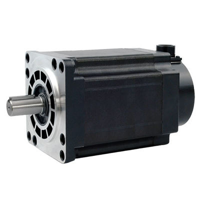
3110HS1600 3 Phase Hybrid Stepper Motor

3110HS1600 3 Phase Hybrid Stepper Motor

Brand Name: PRMCAS
Model Number: 3110HS1600
MOQ: ≥50pcs
Packaging Details: 1pcs for each carton
Payment Terms: Company account based T/T
Detail Information
Place of Origin:
CHINA
Brand Name:
PRMCAS
Certification:
CE, ROHS, CCC
Model Number:
3110HS1600
Frame Size:
Nema 42, 110mm
Phase:
3 Phase
Step Angle:
1.2°
Angle Accuracy:
0.06°
Rated Current:
6.5A
Holding Torque:
16.0N.m
Wires:
6
Highlights:
Top Performance, Long Lifetime, High Speed, High Smoothness
Shaft Type:
Single
Customization:
Supported
Minimum Order Quantity:
≥50pcs
Packaging Details:
1pcs for each carton
Delivery Time:
7-14days for standad version customization 3-4weeks
Payment Terms:
Company account based T/T
Supply Ability:
10000pcs per Month
Highlight:

3110HS1600 Stepper Motor

,

3110HS1600 Hybrid Stepper Motor

Product Description

1. Products Overview

Stepper motor is an executive agency that converts electrical pulses into angle displacement. You can control the angle by controlling the number of pulse to achieve the purpose of accurate position control. At the same time, you can control the speed and acceleration of the motor by controlling the input pulse frequency to achieve the purpose of the speed control.

Step motor, also called as pulse motor is normally classified by structural as: reactive step motors (VR), permanent magnet step motor (PM), and hybrid step motor (HB). Step motor can also be divided into rotation and straight lines according to the form of movement. According to whether there is an encoder, can be divided as open-loop and closed-loop step motors.

Reactive step motor: there are windings on the stator and rotor consisting of soft magnetic materials. The structure is simple, the cost is low, the step distance is small, and it can reach 1.2 °, but the dynamic performance is poor, the efficiency is low, the heating is large, and the reliability is difficult to guarantee.

Permanent Magnet step motor: The rotor of the permanent magnet step motor is made of permanent magnet material, and the rotor is the same as that of the stator. It is characterized by good dynamic performance and large output torque, but this motor has poor accuracy and large steps (generally 7.5 ° or 15 °).

Hybrid Step motor: Hybrid steaming motor integrates the advantages of reaction and permanent magnets both. It has a multi-phase windings, permanent magnet material on the rotor, and multiple small teeth on the rotor and stator to improve the step accuracy. It is characterized by large output torque, good dynamic performance, and small steps, which can meet automation applications which have high precision requirement.


According to the quantity of phases, there are two -phase, three, and five -phase step motors. The most popular is the two-phase hybrid step motor, accounting for about 97%of the market share. The reason is that the two-phase step motor is more cost-effective, and also has satisfactory performance due to subdivision or micro stepping function of its drive.

The basic step angle of a two-phase step motor is 1.8 °/step. Matched with a half-step drive, the step angle is reduced to 0.9 °. Matched with a micro stepping driver, the step angle can be subdivided up to 256 times (0.007 ° per micro step), which can meet the requirement of most applications.


Although the stepper motor and its control technology are currently very mature, if not used properly, there may still be a situation of step loss, i.e. position error. Next, we will analyze the common causes and solutions of position errors.

The reasons for the position error of stepper motors

Large load inertia

When the inertia of the load driven by the stepper motor is large, its inertia will generate inertia force, causing the current waveform output by the stepper motor controller to be inconsistent with the actual required current waveform, resulting in inaccurate position of the stepper motor.

The stepper motor driver is not set correctly

Incorrect settings of the stepper motor driver, such as fine fraction, step angle, and other parameter settings, can also lead to an increase in the position error of the stepper motor.

The pulse signal output by the stepper motor controller is unstable

When the pulse signal output by the stepper motor controller is unstable, it can lead to inaccurate position of the stepper motor. This situation is more common when using long-distance transmission of control signals.

The stepper motor is damaged

The rotor or stator of the stepper motor may be damaged, or the bearings may be damaged, which can lead to positional errors in the stepper motor.

Methods to solve the position error of stepper motors

Control load inertia

The position error of the stepper motor can be reduced by reducing the load inertia. For example, when driving a stepper motor with inertia loads, methods such as installing shock absorbers and changing the load inertia mode can be used to reduce the load inertia.

Set the driver parameters correctly

Correctly set the subdivision and step angle parameters of the stepper motor driver to ensure the position accuracy.

Stable output pulse signal

High precision pulse generators or adjustable filters can be used to stabilize the output pulse signal and reduce the position error of stepper motors.

Replace damaged stepper motor components

When the stepper motor is damaged, it is necessary to replace the corresponding components in order to restore the normal operation of the stepper motor.


The application of Kaifull PRMCAS stepper motors

Mainly used in industries, aerospace, robotics, precision measurement and other fields, such as optoelectronic theodolites for tracking satellites, military instruments, communication and radar equipment, the widespread application of subdivision drive technology makes the phase number of motors not limited by step angle, bringing convenience to product design. At present, in the subdivision drive technology of stepper motors, chopping constant current drive, instrument pulse width modulation drive, and current vector constant amplitude uniform rotation drive control are adopted, greatly improving the operating accuracy of stepper motors and promoting the development of stepper motors in the direction of high-speed and precision in medium and low-power applications.

Kaifull hybrid stepper motors are currently widely used in various automation equipment and instruments such as engraving machines, laser machines, CNC machine tools, textile and clothing machinery, medical equipment, measuring equipment, electronic processing equipment, packaging machinery equipment, etc.

In the field of robotics

In the field of robotics, stepper motors are widely used to control the motion and direction of robot arms. By sending pulse signals on the motor, the robot can easily and accurately pick up or place items.

Printing assembly

In the printing and assembly industry, stepper motors achieve high-quality printing and assembly by controlling the movement of rollers, discs, and other moving parts on the printing machine.

Medical devices

In the field of medical devices, stepper motors are used to control the automated positioning and movement of surgical robots and medical equipment.

3D printing

In 3D printing technology, stepper motors can achieve complex 3D structures and shapes by controlling the movement of the print head.

Industrial automation

In the field of industrial automation, stepper motors are widely used in the control of various equipment, such as engraving machines, laser machines, CNC machine tools, textile and clothing machinery, medical equipment, measuring equipment, electronic processing equipment, packaging machinery and other automation equipment and instruments.

In summary, stepper motors have become an indispensable component in various application fields, helping various devices and machines complete complex actions through their stable motion and precise control.


2. Hybrid Stepper Motor General Technical Specifications


Step Angle 1.2° (3 Phase)
Step Angle Accuracy 0.06°
Shaft Type Single shaft, Dia. 6.35 or 8.0mm (Customizable)
Max. Temperature Rise Less than 80 °C (Rated Current)
Max. Surface Temperatures Max Allowed 100℃
Ambient Temperature -20 °C ~ +50 °C
Insulation Grade 100 MΩ Min. , Class B
Dielectric Strengt 1500 VAC for 1 Minute
Max. Axial Load 150N
Max. Radial Load 490N (10mm from mounting Surface)
Certificates Rohs, CE, CCC (As per Customer Need)


3. Hybrid Stepper motor Performance Datasheet

Model Current Resistance Inductance Holding Torque Cable Type Rotor Inertia Bi/Unipolar Weight Length
  A/Ø Ω/Ø mH/Ø N.m   g.cm2 # of Leads kg mm
3110HS1600-6504S-155 6.5 0.64 9.47 16.0 Connector 13560 Bi (4) 8.9 155


4. Mechanical Dimensions (in mm)

3110HS1600 3 Phase Hybrid Stepper Motor 0


5. Wiring Diagram

3110HS1600 3 Phase Hybrid Stepper Motor 1


6. Torque Speed Curves

3110HS1600 3 Phase Hybrid Stepper Motor 2