Good price  online

products details

Home > Products >
Hybrid Stepper Motor
>
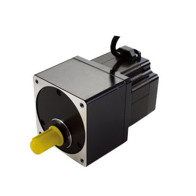
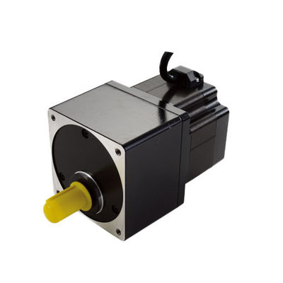
90AHS Integrated With Gearbox Series 2 Phase Hybrid Stepper Motors

90AHS Integrated With Gearbox Series 2 Phase Hybrid Stepper Motors

Brand Name: PRMCAS
Model Number: 90AHS With Gearbox Series
MOQ: ≥50pcs
Packaging Details: 1pcs for each carton
Payment Terms: Company account based T/T
Detail Information
Place of Origin:
CHINA
Certification:
CE, ROHS, CCC
Frame Size:
Nema 35, 90mm
Phase:
2 Phase
Step Angle:
1.8°
Angle Accuracy:
0.09°
Rated Current:
2.1/3.0A
Holding Torque:
2.5/5.0/6.3/7.0/9.0/12.0N.m
Reduction Ratio:
3.6/7.2/9/10/18/36:1
Backlash:
0.5°to1°
Wires:
6
Highlights:
Top Performance, Long Lifetime, High Speed, High Smoothness
Shaft Type:
Single Shaft
Customization:
Supported
Supply Ability:
10000pcs per Month
Highlight:

90AHS Hybrid Stepper Motors

,

Gearbox Series Hybrid Stepper Motors

Product Description

1. Products Overview

Stepper motor is an executive agency that converts electrical pulses into angle displacement. You can control the angle by controlling the number of pulse to achieve the purpose of accurate position control. At the same time, you can control the speed and acceleration of the motor by controlling the input pulse frequency to achieve the purpose of the speed control.

Step motor, also called as pulse motor is normally classified by structural as: reactive step motors (VR), permanent magnet step motor (PM), and hybrid step motor (HB). Step motor can also be divided into rotation and straight lines according to the form of movement. According to whether there is an encoder, can be divided as open-loop and closed-loop step motors.

Reactive step motor: there are windings on the stator and rotor consisting of soft magnetic materials. The structure is simple, the cost is low, the step distance is small, and it can reach 1.2 °, but the dynamic performance is poor, the efficiency is low, the heating is large, and the reliability is difficult to guarantee.

Permanent Magnet step motor: The rotor of the permanent magnet step motor is made of permanent magnet material, and the rotor is the same as that of the stator. It is characterized by good dynamic performance and large output torque, but this motor has poor accuracy and large steps (generally 7.5 ° or 15 °).

Hybrid Step motor: Hybrid steaming motor integrates the advantages of reaction and permanent magnets both. It has a multi-phase windings, permanent magnet material on the rotor, and multiple small teeth on the rotor and stator to improve the step accuracy. It is characterized by large output torque, good dynamic performance, and small steps, which can meet automation applications which have high precision requirement.


According to the quantity of phases, there are two -phase, three, and five -phase step motors. The most popular is the two-phase hybrid step motor, accounting for about 97%of the market share. The reason is that the two-phase step motor is more cost-effective, and also has satisfactory performance due to subdivision or micro stepping function of its drive.

The basic step angle of a two-phase step motor is 1.8 °/step. Matched with a half-step drive, the step angle is reduced to 0.9 °. Matched with a micro stepping driver, the step angle can be subdivided up to 256 times (0.007 ° per micro step), which can meet the requirement of most applications.


Kaifull two-phase, three-phase, and five-phase hybrid step motors are made of high-temperature permanent magnet and high-quality cold-rolled steel sheets. Our stepper motors range is very rich, covering 20mm to 150mm in frame size. At the same time, there are all-in-one step motors that integrated with drivers, closed-loop stepper motor, and with brake stepper motor etc..

Generally speaking, the characteristics of step motor are:

Easy drive.

No matter how the input current changes, as long as the load can be driven, the step motor moves according to the minimum angle.

No feedback signal is required. The step motor moves according to the pulse frequency and quantity given by the drive, and does not need to rely on the motor actual status feedback.

The positioning error does not accumulate. The reason why the stepping motor does not accumulates is because it does not need to know the actual location, but only needs to know the number of rotating steps. Therefore, the step motor only needs to receive the signal of each step, and then move according to the step angle. It is not necessary to know the starting location or target location. This can avoid the problem of accumulating errors. In addition, the working principle of the stepper motor makes the movement discrete and performed from a specific angle without a continuous accumulation error.

Stepper motor driver principle is simple and easy to develop control system.

Step motor has the characteristics of high power density, high output torque, low noise, low vibration and smooth rotation, high energy conversion efficiency, stable and reliable, long life etc. At the same time, our company supports the flexible customization, too.


Although the stepper motor and its control technology are currently very mature, if not used properly, there may still be a situation of step loss, that is, position error etc. Here, we will analyze some problems and solutions.

Losing pulses when changing direction leads to inaccurate positioning

When changing direction, the pulse is lost, which means that it is accurate in any direction, but as soon as the direction is changed, errors accumulate, and the more times it is changed, the more biased it is.

Solution: Generally, stepper drivers have certain requirements for direction and pulse signals. For example, the direction signal is determined a few microseconds before the first rising or falling edge of the pulse (different drivers have different requirements) arrives. Otherwise, there will be a pulse that runs in the opposite direction of the actual required direction. Finally, the problem will appear as it deviates more and more, with smaller subdivisions becoming more prominent. The main solution is to use software to change the logic of the pulse or add a delay.

The initial speed is too high and the acceleration is too large, which sometimes causes stepping loss.

Solution: Due to the characteristics of the stepper motor, the initial speed should not be too high, especially when the load inertia is large. It is recommended to have the initial speed below 1r/s, so that the impact is small. If the same acceleration is too large, it will also have a large impact on the system, which is simple overshoot

Insufficient motor output torque

Solution: Increase the motor current appropriately, increase the voltage of the progressive driver (pay attention to the optional driver), and choose a motor with higher torque.

Environmental electromagnetic interference causes mis-operation of the controller or driver, resulting in inaccurate positioning.

It is necessary to identify the source of disturbance and reduce its electromagnetic interference on the stepper system, such as increasing spatial distance, using shielded wires for signal lines, and ensuring good grounding of the controller or driver to block communication channels and improve its anti-interference ability.

Solutions:

  • Replacing ordinary wires with double shielded wires, the signal lines in the system are separated from wires with high current or high voltage to reduce electromagnetic interference ability.
  • Filter out disturbance waves from the power grid using power filters, and add power filters to the input terminals of major electrical equipment under permissible conditions to reduce interference between devices within the system.
  • It is best to use photoelectric blocking devices for signal transmission between devices. If conditions permit, pulse and directional signals should be transmitted using differential methods with photoelectric blocking. In rational loads (such as electromagnetic relays, solenoid valves), a resistance capacitance absorption or fast discharge circuit is added at both ends. Rational loads can experience a peak voltage of 10-100 times in the initial moment, if the operating frequency is above 20KHZ.


2. Hybrid Stepper Motor General Technical Specifications
 

Step Angle 1.8° (2 Phase)
Step Angle Accuracy 0.09°
Shaft Type Single shaft, Dia. 14 or 12.7mm (Customizable)
Max. Temperature Rise Less than 80 °C (Rated Current)
Max. Surface Temperatures Max Allowed 100℃
Ambient Temperature -20 °C ~ +50 °C
Insulation Grade 100 MΩ Min. , Class B
Dielectric Strengt 1500 VAC for 1 Minute
Max. Axial Load 320N
Max. Radial Load 60N (15mm from mounting Surface)
Certificates Rohs, CE, CCC (As per Customer Need)

 
3. Hybrid Stepper motor Integrated with Gearbox Performance Datasheet

Model

Gear Output

Torque

N.m

Reduction

Ratio

Step

Degree

Gear Side

Current

A/Ø

Resistance

Ω/Ø

Inductance

mH/Ø

Rotor Inertia

g.cm2

Bi/Unipolar

# of Leads

Weight

Kg

Length

Incld. Gear

mm

90AHS250

-3006GR3.6

-130

2. 5 1:3.6 0. 5

3.0

Half

0.49 1.5 1400 Bi(6) 3.0 130

90AHS500

-3006GR7.2

-130

5. 0 1:7.2 0. 25

3.0

Half

0.49 1.5 1400 Bi(6) 3.0 130

90AHS630

-3006GR9

-130

6. 3 1:9 0. 2

3.0

Half

0.49 1.5 1400 Bi(6) 3.0 130

90AHS700

-2106GR10

-130

7. 0 1:10 0. 18

3.0

Half

0.49 1.5 1400 Bi(6) 3.0 130

90AHS900

-2106GR18

-130

9. 0 1:18 0. 1

2.1

Full

0.98 6.0 1400 Bi(6) 3.0 130

90AHS1200

-2106GR36

-130

12..0 1:36 0. 05

2.1

Full

0.98 6.0 1400 Bi(6) 3.0 130


4. Mechanical Dimensions (in mm)
90AHS Integrated With Gearbox Series 2 Phase Hybrid Stepper Motors 0
 
5. Wiring Diagram
90AHS Integrated With Gearbox Series 2 Phase Hybrid Stepper Motors 1
 
6. Torque Speed Curves
90AHS Integrated With Gearbox Series 2 Phase Hybrid Stepper Motors 2

90AHS Integrated With Gearbox Series 2 Phase Hybrid Stepper Motors 3


Good price  online

Products Details

Home > Products >
Hybrid Stepper Motor
>
90AHS Integrated With Gearbox Series 2 Phase Hybrid Stepper Motors

90AHS Integrated With Gearbox Series 2 Phase Hybrid Stepper Motors

Brand Name: PRMCAS
Model Number: 90AHS With Gearbox Series
MOQ: ≥50pcs
Packaging Details: 1pcs for each carton
Payment Terms: Company account based T/T
Detail Information
Place of Origin:
CHINA
Brand Name:
PRMCAS
Certification:
CE, ROHS, CCC
Model Number:
90AHS With Gearbox Series
Frame Size:
Nema 35, 90mm
Phase:
2 Phase
Step Angle:
1.8°
Angle Accuracy:
0.09°
Rated Current:
2.1/3.0A
Holding Torque:
2.5/5.0/6.3/7.0/9.0/12.0N.m
Reduction Ratio:
3.6/7.2/9/10/18/36:1
Backlash:
0.5°to1°
Wires:
6
Highlights:
Top Performance, Long Lifetime, High Speed, High Smoothness
Shaft Type:
Single Shaft
Customization:
Supported
Minimum Order Quantity:
≥50pcs
Packaging Details:
1pcs for each carton
Delivery Time:
7-14days for standad version customization 3-4weeks
Payment Terms:
Company account based T/T
Supply Ability:
10000pcs per Month
Highlight:

90AHS Hybrid Stepper Motors

,

Gearbox Series Hybrid Stepper Motors

Product Description

1. Products Overview

Stepper motor is an executive agency that converts electrical pulses into angle displacement. You can control the angle by controlling the number of pulse to achieve the purpose of accurate position control. At the same time, you can control the speed and acceleration of the motor by controlling the input pulse frequency to achieve the purpose of the speed control.

Step motor, also called as pulse motor is normally classified by structural as: reactive step motors (VR), permanent magnet step motor (PM), and hybrid step motor (HB). Step motor can also be divided into rotation and straight lines according to the form of movement. According to whether there is an encoder, can be divided as open-loop and closed-loop step motors.

Reactive step motor: there are windings on the stator and rotor consisting of soft magnetic materials. The structure is simple, the cost is low, the step distance is small, and it can reach 1.2 °, but the dynamic performance is poor, the efficiency is low, the heating is large, and the reliability is difficult to guarantee.

Permanent Magnet step motor: The rotor of the permanent magnet step motor is made of permanent magnet material, and the rotor is the same as that of the stator. It is characterized by good dynamic performance and large output torque, but this motor has poor accuracy and large steps (generally 7.5 ° or 15 °).

Hybrid Step motor: Hybrid steaming motor integrates the advantages of reaction and permanent magnets both. It has a multi-phase windings, permanent magnet material on the rotor, and multiple small teeth on the rotor and stator to improve the step accuracy. It is characterized by large output torque, good dynamic performance, and small steps, which can meet automation applications which have high precision requirement.


According to the quantity of phases, there are two -phase, three, and five -phase step motors. The most popular is the two-phase hybrid step motor, accounting for about 97%of the market share. The reason is that the two-phase step motor is more cost-effective, and also has satisfactory performance due to subdivision or micro stepping function of its drive.

The basic step angle of a two-phase step motor is 1.8 °/step. Matched with a half-step drive, the step angle is reduced to 0.9 °. Matched with a micro stepping driver, the step angle can be subdivided up to 256 times (0.007 ° per micro step), which can meet the requirement of most applications.


Kaifull two-phase, three-phase, and five-phase hybrid step motors are made of high-temperature permanent magnet and high-quality cold-rolled steel sheets. Our stepper motors range is very rich, covering 20mm to 150mm in frame size. At the same time, there are all-in-one step motors that integrated with drivers, closed-loop stepper motor, and with brake stepper motor etc..

Generally speaking, the characteristics of step motor are:

Easy drive.

No matter how the input current changes, as long as the load can be driven, the step motor moves according to the minimum angle.

No feedback signal is required. The step motor moves according to the pulse frequency and quantity given by the drive, and does not need to rely on the motor actual status feedback.

The positioning error does not accumulate. The reason why the stepping motor does not accumulates is because it does not need to know the actual location, but only needs to know the number of rotating steps. Therefore, the step motor only needs to receive the signal of each step, and then move according to the step angle. It is not necessary to know the starting location or target location. This can avoid the problem of accumulating errors. In addition, the working principle of the stepper motor makes the movement discrete and performed from a specific angle without a continuous accumulation error.

Stepper motor driver principle is simple and easy to develop control system.

Step motor has the characteristics of high power density, high output torque, low noise, low vibration and smooth rotation, high energy conversion efficiency, stable and reliable, long life etc. At the same time, our company supports the flexible customization, too.


Although the stepper motor and its control technology are currently very mature, if not used properly, there may still be a situation of step loss, that is, position error etc. Here, we will analyze some problems and solutions.

Losing pulses when changing direction leads to inaccurate positioning

When changing direction, the pulse is lost, which means that it is accurate in any direction, but as soon as the direction is changed, errors accumulate, and the more times it is changed, the more biased it is.

Solution: Generally, stepper drivers have certain requirements for direction and pulse signals. For example, the direction signal is determined a few microseconds before the first rising or falling edge of the pulse (different drivers have different requirements) arrives. Otherwise, there will be a pulse that runs in the opposite direction of the actual required direction. Finally, the problem will appear as it deviates more and more, with smaller subdivisions becoming more prominent. The main solution is to use software to change the logic of the pulse or add a delay.

The initial speed is too high and the acceleration is too large, which sometimes causes stepping loss.

Solution: Due to the characteristics of the stepper motor, the initial speed should not be too high, especially when the load inertia is large. It is recommended to have the initial speed below 1r/s, so that the impact is small. If the same acceleration is too large, it will also have a large impact on the system, which is simple overshoot

Insufficient motor output torque

Solution: Increase the motor current appropriately, increase the voltage of the progressive driver (pay attention to the optional driver), and choose a motor with higher torque.

Environmental electromagnetic interference causes mis-operation of the controller or driver, resulting in inaccurate positioning.

It is necessary to identify the source of disturbance and reduce its electromagnetic interference on the stepper system, such as increasing spatial distance, using shielded wires for signal lines, and ensuring good grounding of the controller or driver to block communication channels and improve its anti-interference ability.

Solutions:

  • Replacing ordinary wires with double shielded wires, the signal lines in the system are separated from wires with high current or high voltage to reduce electromagnetic interference ability.
  • Filter out disturbance waves from the power grid using power filters, and add power filters to the input terminals of major electrical equipment under permissible conditions to reduce interference between devices within the system.
  • It is best to use photoelectric blocking devices for signal transmission between devices. If conditions permit, pulse and directional signals should be transmitted using differential methods with photoelectric blocking. In rational loads (such as electromagnetic relays, solenoid valves), a resistance capacitance absorption or fast discharge circuit is added at both ends. Rational loads can experience a peak voltage of 10-100 times in the initial moment, if the operating frequency is above 20KHZ.


2. Hybrid Stepper Motor General Technical Specifications
 

Step Angle 1.8° (2 Phase)
Step Angle Accuracy 0.09°
Shaft Type Single shaft, Dia. 14 or 12.7mm (Customizable)
Max. Temperature Rise Less than 80 °C (Rated Current)
Max. Surface Temperatures Max Allowed 100℃
Ambient Temperature -20 °C ~ +50 °C
Insulation Grade 100 MΩ Min. , Class B
Dielectric Strengt 1500 VAC for 1 Minute
Max. Axial Load 320N
Max. Radial Load 60N (15mm from mounting Surface)
Certificates Rohs, CE, CCC (As per Customer Need)

 
3. Hybrid Stepper motor Integrated with Gearbox Performance Datasheet

Model

Gear Output

Torque

N.m

Reduction

Ratio

Step

Degree

Gear Side

Current

A/Ø

Resistance

Ω/Ø

Inductance

mH/Ø

Rotor Inertia

g.cm2

Bi/Unipolar

# of Leads

Weight

Kg

Length

Incld. Gear

mm

90AHS250

-3006GR3.6

-130

2. 5 1:3.6 0. 5

3.0

Half

0.49 1.5 1400 Bi(6) 3.0 130

90AHS500

-3006GR7.2

-130

5. 0 1:7.2 0. 25

3.0

Half

0.49 1.5 1400 Bi(6) 3.0 130

90AHS630

-3006GR9

-130

6. 3 1:9 0. 2

3.0

Half

0.49 1.5 1400 Bi(6) 3.0 130

90AHS700

-2106GR10

-130

7. 0 1:10 0. 18

3.0

Half

0.49 1.5 1400 Bi(6) 3.0 130

90AHS900

-2106GR18

-130

9. 0 1:18 0. 1

2.1

Full

0.98 6.0 1400 Bi(6) 3.0 130

90AHS1200

-2106GR36

-130

12..0 1:36 0. 05

2.1

Full

0.98 6.0 1400 Bi(6) 3.0 130


4. Mechanical Dimensions (in mm)
90AHS Integrated With Gearbox Series 2 Phase Hybrid Stepper Motors 0
 
5. Wiring Diagram
90AHS Integrated With Gearbox Series 2 Phase Hybrid Stepper Motors 1
 
6. Torque Speed Curves
90AHS Integrated With Gearbox Series 2 Phase Hybrid Stepper Motors 2

90AHS Integrated With Gearbox Series 2 Phase Hybrid Stepper Motors 3